Head Phone IR Break
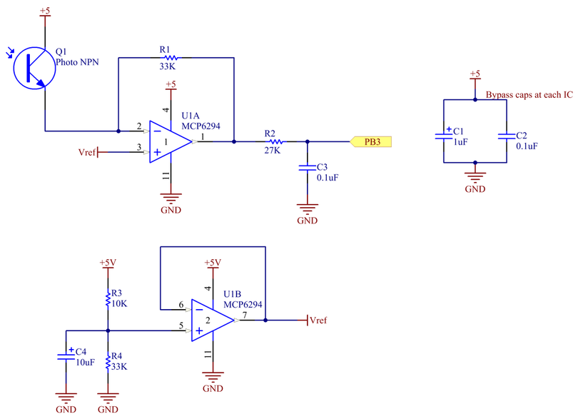
Initially we attempted to use a comparator circuit to create a 0-5V digital signal but this led to spurious headphones placed events upon startup. Instead we decided to use a simple trans-resistive circuit that outputs about 3.8V when blocked and almost GND when open. Finally we applied a low pass filter to this output to remove high frequency noise introduced when running the motors.
Audio I/O
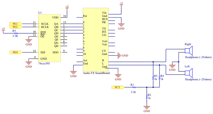
The shift register allows for triggering of up to 8 audio files on the Adafruit SoundBoard. We loaded our 4 desired files as inputs 0-3 so we connected those to the shift register. In order to play tones via the TIVA PWM on the same pair of headphones, we merged the signal with each output channel of the SoundBoard.
LED Feed-Back
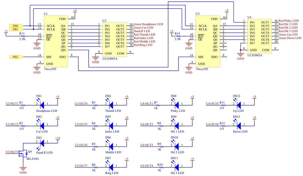
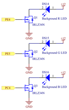
We used two shift registers in series to control 13 LED outputs via only 3 TIVA pins. This saved us a ton of space on the TIVA and allowed for simple control via our shift register interface functions. We used an array of darlington transistors to source current to the LEDs to limit current draw from the TIVA (also provides a convenient method to test for blown LEDs). We also used N-type MOSFETS to control the variable intensity of the RGB channels of analog LED strip. This allowed us to vary the color of the back-light to show passage of time and create visual displays for celebration and defeat.
Motor/Servo Control
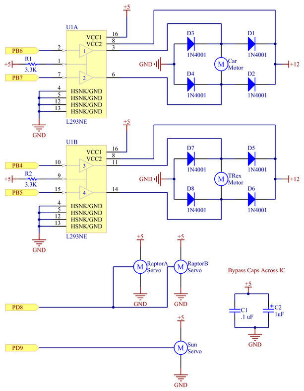
Two half-bridges and snubbing diodes were used to proved bi-directional control of each motor.
The servos are driven directly via the TIVA PWM outputs as they already contain the circuitry required to control position via the PWM signal.
The servos are driven directly via the TIVA PWM outputs as they already contain the circuitry required to control position via the PWM signal.
IR Range Finder
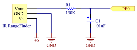
We added a low pass filter to the analog output from the range finder to remove high frequency noise we were seeing. We set the cutoff frequency above the most rapid hand movements we expect to prevent attenuation of the desired signal.
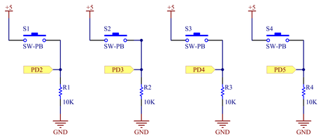
Note Buttons
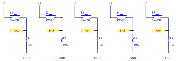
Momentary, normally open, push button switches that normally read low. Goes high when button pressed.
Limit Switches
Momentary, normally open, limit switches that normally read low. Goes high when limit reached.
Car Reed Switch
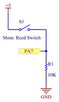
Momentary, normally open, magnetic reed switch that normally reads low. Goes high when magnet on car is within range.
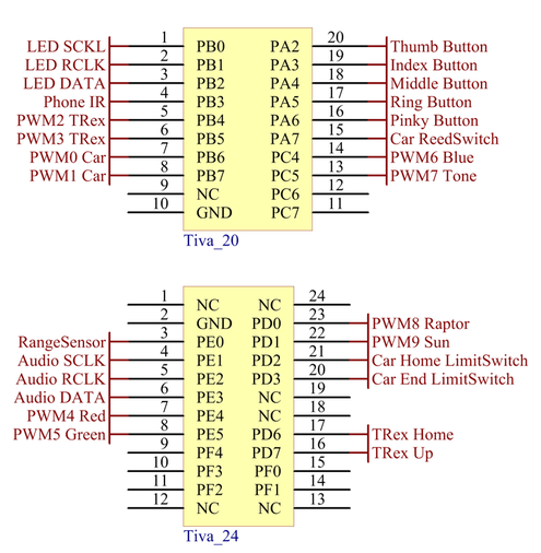
TIVA Connections